GENERAL PROGRAMMING
PID Control
| Date Published: | |
| Last Modified: |
Overview
PID control is a very common technique for controlling a system in which you have a desired set-point for the system to be in, and are able to control this with one variable. PID is an acronym for Proportional-Derivative-Integral, and describes the three mathematical processes used to decide on a output to the control system.
You change the dynamics of the PID control loop by varying three parameters, the proportional, integral and derivative constants.
How PID Works
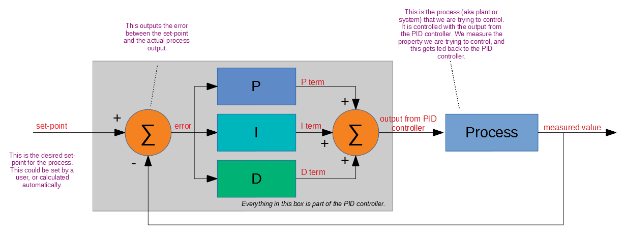
PID is a industry-standard way of controlling a system, given a single input control parameter (e.g. duty cycle of heater) and a single variable that you want controlled (e.g. temperature of the heater).
A PID controller compares a set-point (decided on by the user, e.g. this may the temperature you want the room to be at). It then compares this with the measured system variable (the actual temperature of the room). The difference between the set-point and the measured variable is called the error.
This error is what is fed into the P (proportional), I (integral) and D (derivative) blocks.
The Maths
The standard PID equation is:
The error is always defined as the setpoint value - acutal value, so the error is positive when the actual value is less than what it needs to be. It is defined by the following equation:
where:
\(e\) = error
\(u(t)\) = setpoint value
\(y(t)\) = actual value
This PID equation is in the continuous time domain. However, most PID control loops are implemented digitally. The discrete equation is written:
where:
\(T\) is the time period between samples
This equation is suitable for implementing in code. There also exists the Z transformation of the equation, but this obscures the physical meaning of the parameters used in the controller.
Tuning Methods
Coming soon…
Integral Windup
Integral windup is a common problem with PID controllers. It is when a sudden change in the set-point or large disturbance on the output (really anything that causes a large error between where you are and where you want to be), causes the integral term to build up (remember that the integral term accumulates errors). Once you have reached where you want to be, the integral term has to “unwind”, and will drive the output past the setpoint until the error-time product is unwound.
Ways of preventing integral windup:
Limit Integral Effort To Fixed Values
This is the simplest form of preventing integral windup. Windup is preventing by limiting the integral effort to fixed maximum/minimum values. If the integral efforts begins to exceed the set max/min values, it is limited to these max/min values. Note that the integral effort is not reset. This is a common point of confusion, as sometimes the process of preventing integral windup is called “resetting”.
Limit Integral Effort Based On Output Limits
If output limits exist (they should for most real-world processes), the integral effort can be limited when the output hits it’s limits.
For example, say the P, I and D terms were contributing the following effort to the output:
- P = 6
- I = 5
- D =2
Lets pretend the output is limited to 10. P + I + D = 13, so the output is going to be saturated. The I effort is likely to be even larger next iteration (assuming we haven’t reached our set-point yet) and so the output will saturate even more. To prevent this, we could limit the I value so that the sum of all three just hits the saturation limit, e.g. I would be set to 2.
Be careful not to set the integral term to a negative value! This could potentially occur if the P + D term were already larger than the saturated value.
Worked Example
Lets assume a mass/spring/damper process (aka plant or system) which consists of a mass attached to a fixed wall by spring and damper. We want to control the position of the mass, relative to it’s resting point (which will be when the spring exerts no force).
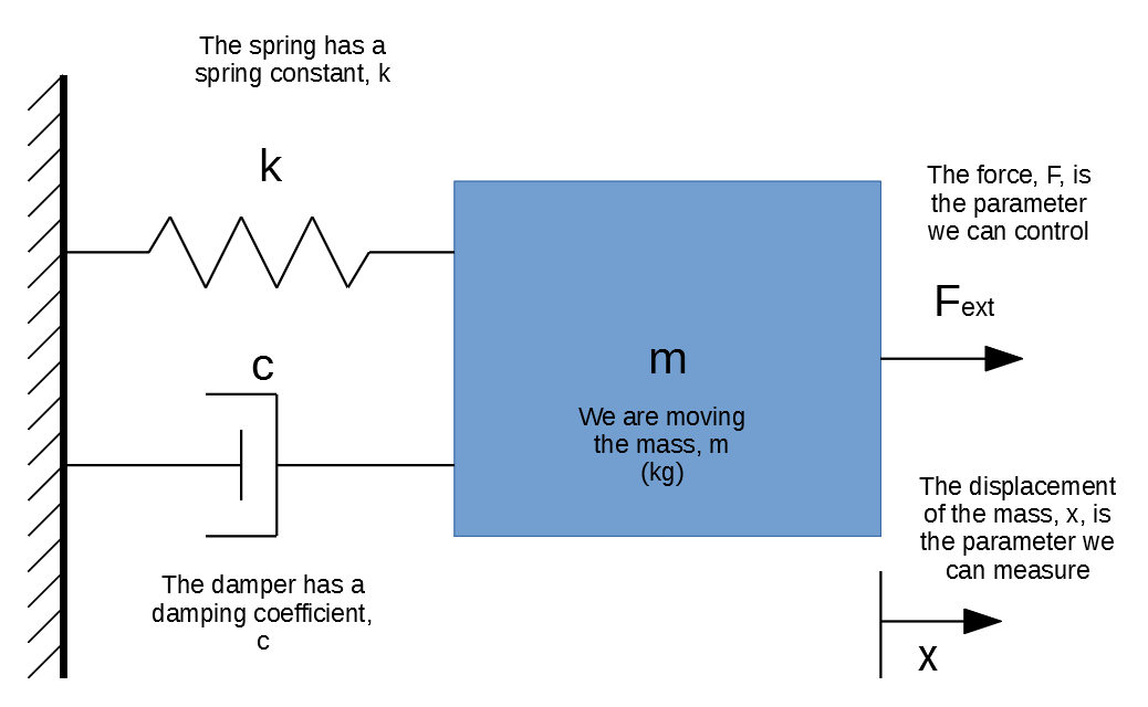
A mass-spring-damper system, which is commonly used to demonstrate PID control and appropriate tuning.
The mass m is 2kg. The spring has a spring constant, k, which is 5N/m. The damping coefficient is 3 Ns/m.
We can model the system using Newton’s equation:
Summing up the forces on the mass \(m\) gives:
Substituting in the equations for the spring and damper give:
where:
\(x\) is the displacement
\(\dot{x}\) is the first derivative of \(x\) (i.e. velocity)
\(\ddot{x}\) is the second derivative of \(x\) (i.e. acceleration)
We can simulate this system in code by discretizing the system into small time steps, and assume linear values for the acceleration and velocity over these small time steps.
The way the simulation works:
Assume starting conditions of displacement, velocity and acceleration are 0.
\(F_{ext}\)is the control variable (set by the PID controller).Determine a time step,
\( \Delta{T} \). Then for each time step:Calculate the force exerted by the spring and damper.
\( F_{spring} = kx \)\( F_{damper} = c\dot{x} \)Calculate the acceleration for this time step:
\( \ddot{x} = \frac{F_{ext} - F_{spring} - F_{damper}}{m} \)Calculate the change in velocity and displacement for this time step:
\( \Delta{\dot{x}} = \ddot{x} \Delta{T} \)\( \Delta{x} = \dot{x} \Delta{T} \)Note that these are changes in velocity in displacement, so to calculate the velocity and displacement you add this change to the stored velocity/displacement state.
Once the values for the velocity and displacement are updated, repeat steps 3-5 for the next time step.
\(F_{spring}\)and\(F_{damper}\)will calculated for the next time step using these updated velocity and displacement values.
Firmware Modules
If you are looking for PID code for an embedded system, check out my Pid project on GitHub (CP3id). It is written in C++ and designed to be portable enough to run on many embedded systems, as well as Linux.
External Links
A really cool open-source hardware project is the osPID Kit which is sold at RocketScream. It looks really swank in it’s acrylic blue enclosure.
Improving The Beginners PID: Introduction is a great set of articles explaining PID control loops and use Arduino code examples to supplement the explanations.
Practical Process Control: Proven Methods And Best Practices For Automated Process Control has lots of useful information on PID.
Related Content:
- PID Tuner Tool Released In NinjaCalc
- S3
- Azure
- An Introduction To Asynchronous Programming In Python
- Installing Python