PCB DESIGN
Mouse Bites
| Date Published: | |
| Last Modified: |
Overview
Mouse bites are a set of drill holes arranged in a small semi-circle on the edge of the board. They are used when the board is going to be panelised, routed, and populated with a pick and place machine.
Schematic Symbol
There is no standardised symbol for mouse bites. In fact, mouse bites may be directly added to the PCB using hole/via primitives and not feature on the schematics at all (this is up to the designers discretion).
I use the following symbol to define mouse bites on schematics:

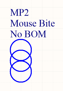
A schematic symbol for a mouse bite. Mouse bites may be added directly to the PCB and not feature on the schematics.
PCB Considerations
There is no routing around the mouse bite (see the break in the purple line in the image below), resulting in the PCBs staying together. However, the drilled holes makes it easy to snap the PCBs out of the panel once the boards have been populated and soldered.
Related Content:
- Pads, Vias And Holes
- PCB Design Tools
- PCB Layers
- TO-273AA Component Package
- How To Calculate Maximum Track Current