COMPONENT PACKAGES
SOT-223 Component Package
| Date Published: | |
| Last Modified: |
Overview
| Name | SOT-223 (Small-outline Transistor 223) |
| Synonyms |
|
| Variants |
|
| Similar To | |
| Mounting | SMD |
| Pin Count | 3, 4, 5 (excl. tab) |
| Pitch | n/a |
| Solderability | Easily solderable by hand |
| Thermal Resistance | SOT-223-3
|
| Dimensions | n/a |
| 3D Models | n/a |
| Common Uses |
|
Conflicting Naming Conventions
This page associates the x in SOT-223-x to stand for the number of pins excluding the tab. This is the most popular convention.
SOT-223-3
The SOT-223-3 (TO-261AA) component package is the most common variant within the SOT-223 family. It looks similar to the SOT-23 package, but with a tab on one side instead of legs.

It is commonly used for medium-power linear regulators and load switches.
Thermal Resistance
Texas Instruments gives the following thermal resistance data for the SOT-223-3 package (taken from http://www.ti.com/lit/ds/symlink/tps7b6933-q1.pdf, as of Dec 2017, URL is unavailable).
| Property | Symbol | Value |
|---|---|---|
| Junction-to-ambient thermal resistance | \(R_{\theta JA}\) | \(64.2^{\circ}C/W\) |
| Junction-to-case (top) thermal resistance | \(R_{\theta JC(top)}\) | \(46.8^{\circ}C/W\) |
| Junction-to-board thermal resistance | \(R_{\theta JB}\) | \(13.3^{\circ}C/W\) |
| Junction-to-top characterisation parameter | \(R_{\psi JT}\) | \(6.3^{\circ}C/W\) |
| Junction-to-board characterisation parameter | \(R_{\psi JB}\) | \(13.2^{\circ}C/W\) |
All of the parameters in the above table were measured with the SOT-223-3 package soldered to a JEDEC standard high-K profile, JESD 51-7, 2s2p four layer board with 2-oz copper. The copper pad was soldered to the thermal land pattern.

Standard Linear Regulator Pinout
The SOT-223-3 package is commonly used for small, medium-power linear regulators. There is a de-facto standard pinout that many manufacturers use when incorporating a linear regulator into the SOT-223-3 package:

The de-facto standard pinout for a linear regulator inside a SOT-223-3 package. This image also shows the standard PCB footprint used to achieve a low thermal resistance. Image from http://www.ti.com/.
Standard Load Switch Pinout
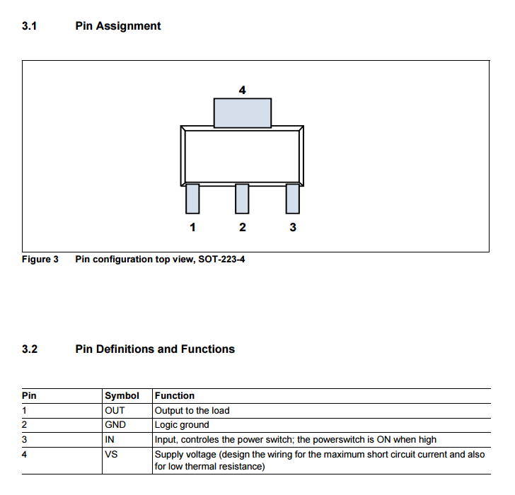
The SOT-223-3 package is commonly used for smaller low and high-side load switches. As such, there is a de-facto standard pinout that many manufacturers use for load switches in the SOT-223-3 package:

The de-facto standard pinout for a load switch in a SOT-223-3 package. Image from http://www.infineon.com/.
SOT-223-4
This variant can be confused with the three pin and one pad variant (SOT-223-3) if you decide to count the pad as well as the pins in the number.

SOT-223-5
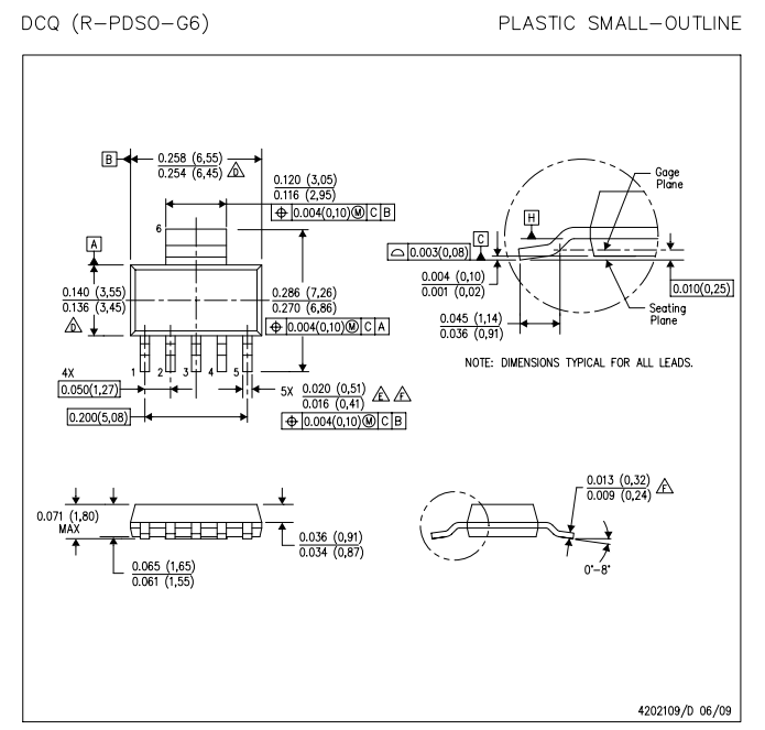
Dimensions
Below are the dimensions of the SOT-223-5 package as specified by Texas Instruments.

Footprint (Land Pattern)
Below is the recommended footprint (land pattern) for the SOT-223-5 component package as specified by Texas Instruments.

A recommended footprint (land pattern) for the SOT-223-5 component package. Image from http://www.ti.com/.
Thermal Resistance
Below is a graph showing the thermal resistance of the SOT-223-5 package with varying copper area.

Graph of thermal resistance vs. copper area for the SOT-223-5 component package. Image from http://www.ti.com/.
As you can see, as the copper area increases, the thermal resistance decreases asymptotically to around \(55^{\circ}{\rm C}/W\).
Related Content:
- TO-261AA Component Package
- PCB Layers
- TO-273AA Component Package
- How To Calculate Maximum Track Current
- SOT-665 Component Package
Tags:
- component packages
- PCB design
- SOT-223
- DCQ
- DCY
- MP04A
- PG-SOT-223-4
- TO-261-4
- R-PDSO-G6
- footprint
- land pattern
- PCBs
- dimensions
- linear regulator