COMPONENT PACKAGES
DIP Component Package
| Date Published: | |
| Last Modified: |
Overview
| Name | Dual In-Line Package |
| Synonyms |
|
| Variants | |
| Similar To | |
| Mounting | TH |
| Pin Count | 4-64 |
| Pitch | 2.54mm (0.1mil) |
| Solderability | Easiest chip package to solder! Perfect for prototyping, fits into standard 100mill pitch prototype board. |
| Thermal Resistance | |
| Land Area | The general land area formula for DIP packages A = ((n/2)*2.54) * (width + 1.65mm) where n is the number of pins and the width is the rated package width in mm (e.g. 7.62 (300mil), 15.24 (600mil)).
|
| Height | 5.0mm |
| 3D Models | |
| Common Uses |
|
Comments
The most common through-hole IC package. Now mostly superseded by SMT packages. Has standard 100mill pitch spacing. The two rows of legs are usually 300mill (thin-type), or 600mill (fat-type) apart (400mil and 900mil variants are also present). The 600mill package is usually reserved for the larger pin variants. As well as standard through-hole mounting, they can also be inserted into a socket, either by friction or clamping (zero insertion force). Pin numbering is counter-clockwise from the top-left.
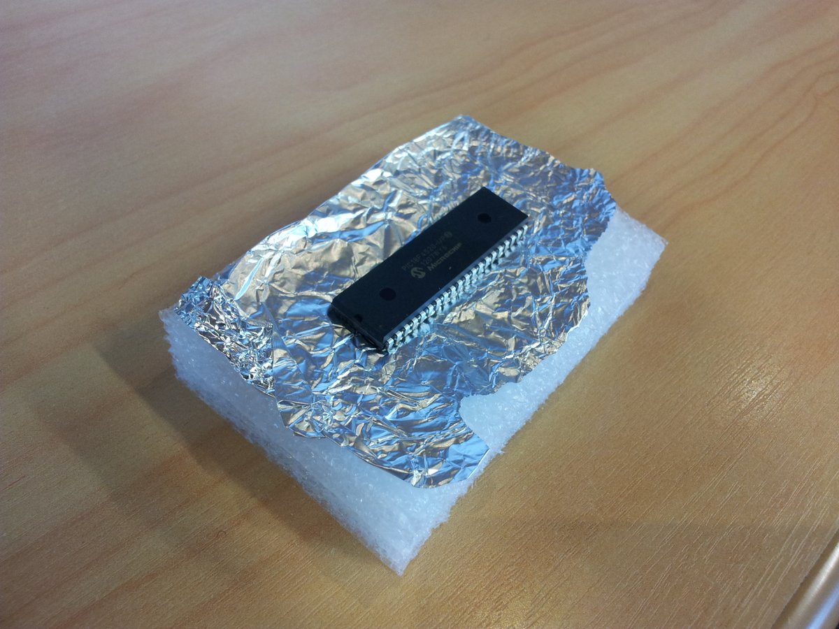
Anti-static packaging can easily be made for DIP packages with foam and aluminium foil as shown in the picture below.

Components other than ICs can also use this footprint (although they typically have different packages). One example are some 7-segment, 4-digit LCD character displays, which use the DIP-600-12 footprint.
3D Renders

Related Content:
- QIP Component Package
- TO-273AA Component Package
- SOT-665 Component Package
- SOT-89 Component Package
- TO-5 Component Package