POWER REGULATORS
Linear Regulators
| Date Published: | |
| Last Modified: |
Overview
Linear regulators are great when you want a cheap, low power voltage regulation solution. They can also be used on the output of a DC/DC converter to reduce the ripple (the ripple will be reduced by the high PSRR).

Important Parameters
- Maximum current (A)
- Output voltage (or voltage range if adjustable,
\(V_{out}\)) - Input voltage range
\(V_{in}\) - Protection circuitry (current limit, input polarity reversal, thermal limit)
- Junction-to-ambient thermal resistance of linear reg package (
\(T_{j-a}\), °C/W) - Power-supply rejection ratio (
\(PSRR\), dB) - Maximum operating temperature
Thermal Considerations
The power lost as heat through a linear regulator is:
where:
\( V_{out} \) is the output voltage
\( V_{in} \) is the input voltage
\( I \) is the current through the regulator.
The regulator has to be able to dissipate this power without exceeding the maximum operating temperature. The temperature that the linear regulator will operate at is given by:
where:
\( T_{j-a} \) is the junction-to-ambient thermal resistance
\( T_a \) is the ambient temperature
Protection
While you easily blow up regulators in the 1990’s, even the very cheap modern-day regulators have built in protection circuitry which makes them basically indestructable. Most feature excess current protection, thermal protection (most turning off above if their die temperature exceeds 150-170°C), short-circuit protection, reverse-polarity protection, and input disconnect (reverse current flow) protection. One of the only ways to kill them is over-voltage on either the input or output.
Bypass Capacitor
Variable output-voltage linear regulators usually have a feedback pin for setting the voltage. This pin is normally connected to the centre of a resistor divider between the output pin and ground. The ratio of the resistances determines the output voltage. When using these types of linear regulators, it can help to have a bypass capacitor between the output pin and the feedback pin. These are also known as feedforward capacitors.
Adding capacitance here helps improve the AC characteristics of the linear regulator, which includes:
- Better transient response to load changes
- Increases the PSRR (power supply rejection ratio)
- Decreases the noise added to the line by the linear regulator
A typical value of a bypass capacitor is \(10nF\).
DDR Termination Regulators
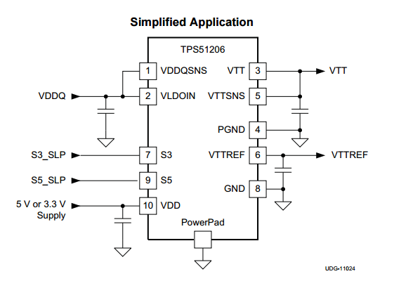
DDR termination regulators are special-purpose linear regulators designed for powering DDR memory ICs. They usually provide the multiple voltage rails that are required to drive DDR memory, along with the power control logic required to meet the DDR spec. (incl. suspend to RAM, suspend to disk states).

The Texas Instruments TPS51206 IC, a DDR termination regulator (linear). Image from http://www.ti.com/.
DDR memory draws current in quick surges of around 2-3A. Most DDR termination regulators support both the sinking and sourcing of current, which means they can clamp the voltage if an overshoot occurs due to a fast switching transient. Standard linear regulators cannot do this, and only source current.
Example Devices
The Texas Instruments TPS7A4001 is a high-voltage (100V) linear regulator which can provide up to 50mA of current.