POWER REGULATORS
Charge Pumps
| Date Published: | |
| Last Modified: |
Overview
A charge pump (also known as a switched capacitor circuit) is a voltage-converting circuit that uses capacitors, diodes, and a oscillating switch to move charge from one capacitor to another.
A single capacitor/diode configuration (with additional smoothing capacitor on the output) doubles the input voltage. Multiple elements can be connected together to create larger voltage increases.
Negative Voltage Bias For Op-Amps
Charge pumps can be used to provide the negative voltage to op-amps. They suit this application since op-amp power supplies typically require little current (1-20mA), and can generate the negative voltage from the main, higher-current, positive power source.
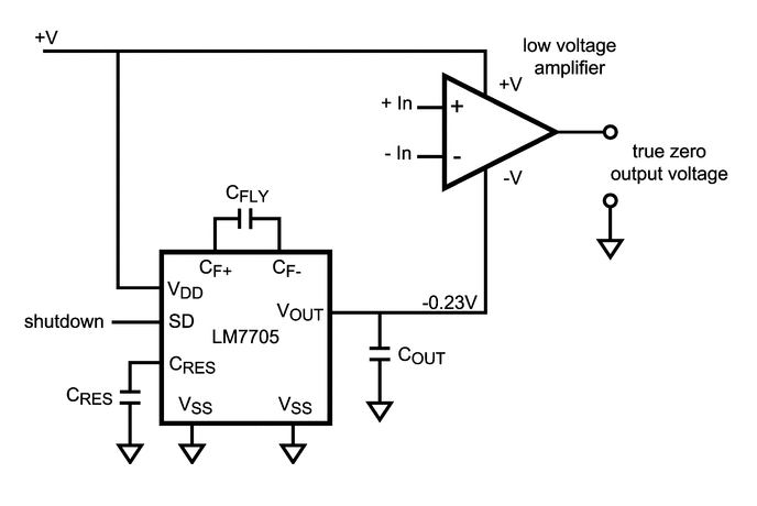
Special charge pumps exist that only produce a very small negative voltage (e.g. -250mV), for providing the negative power supply to rail-to-rail “single-supply” op-amps so that they can output a true 0V. More on this on the Op-amps page.

The typical application schematic for the Texas Instruments LM7705, a 'Low-Noise Negative Bias Generator' for the negative supply of an op-amp. This allows the op-amp to output true 0V. Image from http://www.ti.com/.
LED Drivers
Some LED drivers feature charge pumps to boost the supply voltage to a proper level to drive the LEDs. Charge pumps are usually feature in low power (20mA per channel) LED drivers, that may need to boost say, a +3.3V supply to +4.5V to drive an LED with the correct current. The NCP1840 8-Channel Charge-Pump I2C LED Driver by On Semiconductor is one such example.