COMPONENTS
Optical Isolators
| Date Published: | |
| Last Modified: |
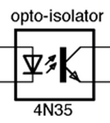
Schematic Symbol
A commonly used schematic symbol for an optical isolator is shown below:

The Current-Transfer Ratio
The current-transfer ratio of a photo-transistor based optical isolator tells you how well it amplifies an input signal to an output signal.
For optical isolators with a single phototransistor driver, the current-transfer ratio is normally in the 20-120% range.
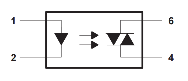
Phototriac Outputs
Some optical isolators have phototriac outputs instead of the normal phototransistor output. A phototriac is a triac whose gate is controlled by the incoming light source, essentially the same as what a phototransistor is to a transistor.

The internal schematic of an optical isolator with a phototriac output driver rather than a phototransistor. Image from http://www.ti.com/.
The outputs of phototriac optical isolators usually go on to drive power TRIACs which switch a mains powered load.
Component Packages
To achieve good isolation, different-net pins must be kept well away from each other to prevent arcing. This prevents many small-pitch packages from being used for optical isolators.
The two most common packages used for optical isolation components are the through-hole DIP package and the surface-mount SOIC package.
Related Content:
- TO-273AA Component Package
- March 2016 Updates
- Mouse Bites
- SOT-665 Component Package
- SOT-89 Component Package