COMPONENTS
Op-Amps
| Date Published: | |
| Last Modified: |
Overview
At it’s most basic level, an operational amplifier (op-amp) is a discrete analogue integrated circuit which acts as a voltage-amplifier with very high gain.
Note that an op-amp’s gain can be adjusted with the appropriate external circuitry (the op-amp’s internal gain does not change, but the gain of the entire circuit does). It can also be converted into a current amplifier.
Schematic Symbol
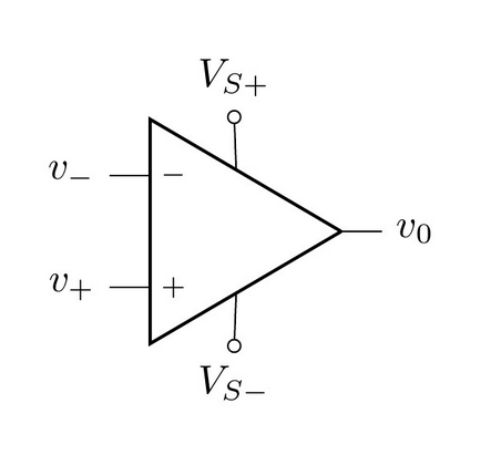
An op-amp is commonly drawn on schematics as:

You may see this symbol with or without the voltage supply pins \( V_{S+} \) and \( V_{S-} \). If they are not present, it is assumed that they are connected up to a power source which should be obvious from the design intent.
Uses
- Buffers
- Linear amplifiers, non-linear amplifiers
- Pre-amplifiers (amplifier’s with a input voltage of 10mV or less)
- Analogue mathematical operations (differentiators, integrators, summer, subtracters, e.t.c)
- Voltage to current (transconductance) and current to voltage conversions (transimpedence)
Voltage Follower (aka Buffer)
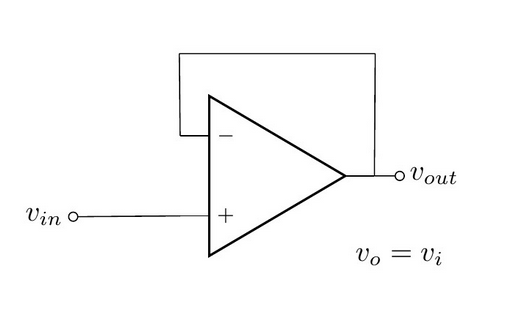
A voltage follower (also known as a buffer) is one of the most basic circuits you can make with an op-amp.

As shown in the above diagram, the output voltage is the same as the input voltage (\(v_{o} = v_{i}\)). Well isn’t this pointless? No, the key point to a voltage follower/buffer is that it can convert a high-impedance input into a low impedance output. Practically, this means that you can now sink/source more current from the output without the voltage changing. Buffers are great for boosting signals that travel across long distances, or for signals which get split and go to many devices (this is called fan-out, and is common with digital clock signals).
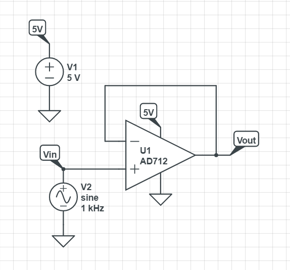
A simulation schematic for a voltage-follower op-amp is shown below:

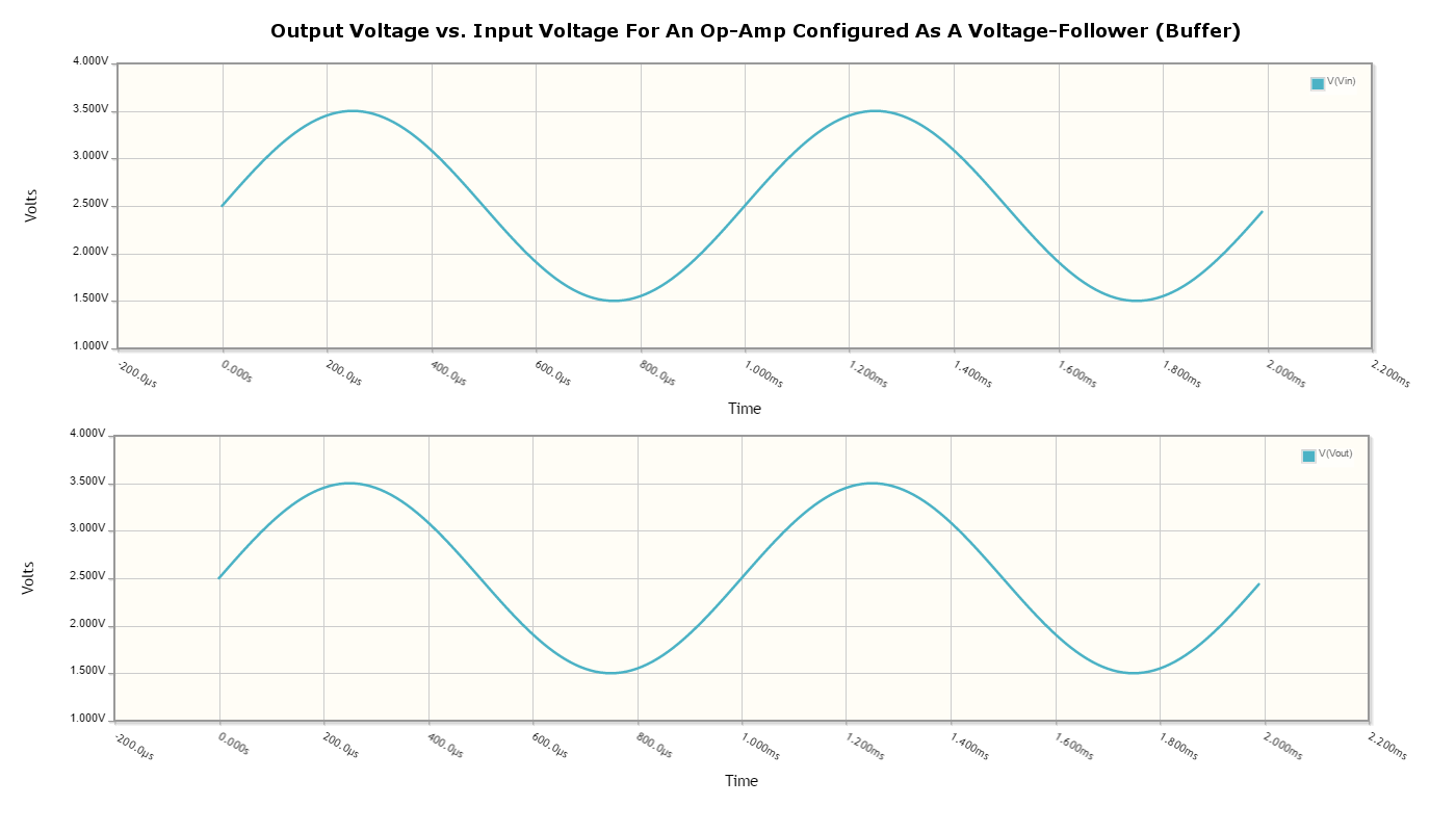
The results of the simulation:

The simulation results for an op-amp configured as a voltage-follower (buffer). Note how the output voltage mirrors the input voltage exactly.
Non-Inverting Amplifier
A op-amp in the non-inverting amplifier configuration is shown below.

The equation for the gain of the non-inverting amplifier is:
Notice the \(1\) in the gain equation? This means that no matter what you set the resistors \(R_f\) and \(R_i\) to, you can never get a gain which is less than one. This is one of the disadvantages of the non-inverting amplifier (you can have a gain of less than one with an inverting amplifier).
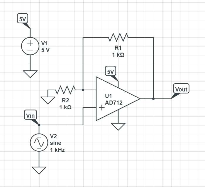
Here is a simulation schematic (circuit) for a non-inverting op-amp amplifier running from a single-ended supply. Because R1 (\(R_f\)) and R2 (\(R_i\)) are both \(1k\Omega\), the op-amp has a gain of:

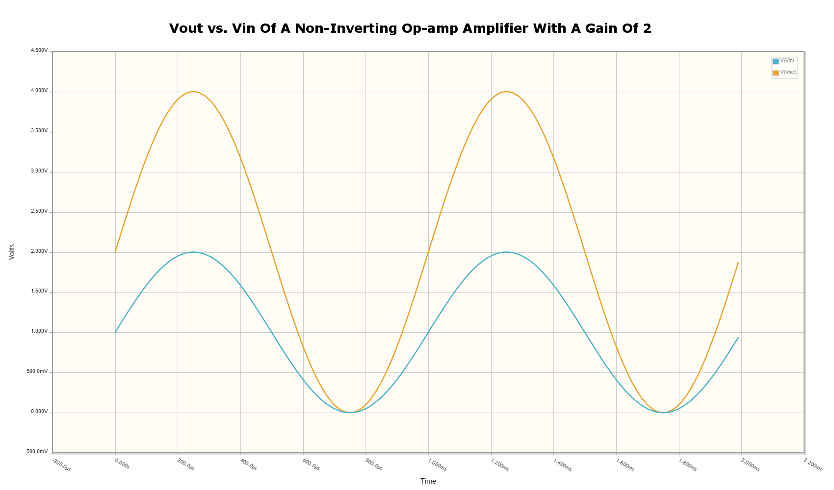
The results of the simulation are shown below. As you can see, the output voltage \(V_{out}\) is exactly twice the input voltage \(V_{in}\).

Inverting Amplifier
A op-amp amplifier in the inverting configuration is shown below:

The equation for the gain of an inverting amplifier is:
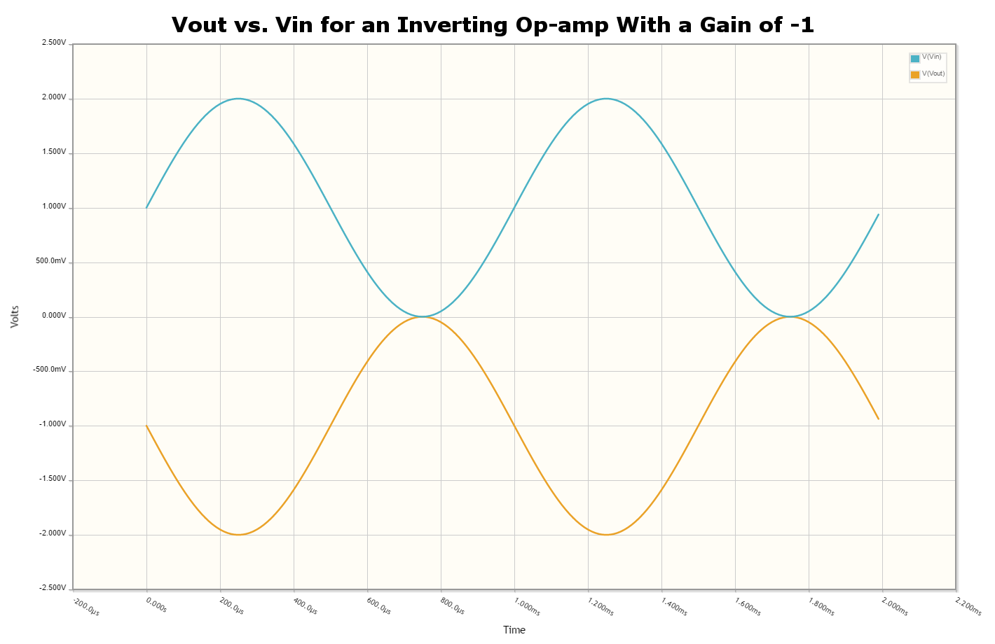
The negative sign is to show that the output is the inverse polarity of the input. Notice that, unlike the non-inverting amplifier, an inverting amplifier lets you obtain a gain of less than 1.
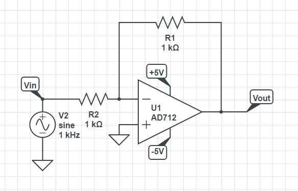
Below is the schematic used for simulating the behaviour of an inverting op-amp. Note how is requires a negative voltage power supply.

And below are the simulation results for the above schematic:

Differential Amplifier
A differential amplifier amplifies the difference between two electrical signals.

The output voltage is given by the equation:
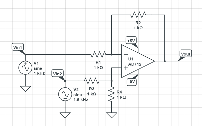
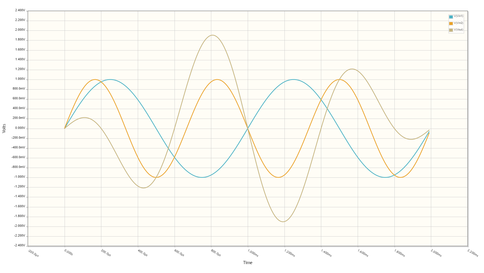
Below is a schematic for simulating the behaviour of a differential op-amp:

This schematic produces the following results:

Integrator
It’s output voltage is proportional to the integral of the input voltage w.r.t. time. The figure below shows an ideal op-amp based integrator.

However, this circuit is normally not practical in real world situations. Any errors such as the output offset voltage and input bias current (which all op-amps invariably have), as well as a non-perfect input signal with small amounts of DC bias, will cause the output to drift, until it reaches saturation.
A way to fix this problem is to insert a high-valued feedback resistor, \(R_f\), to limit the DC gain, as well as a resistor, \(R_{bias}\), on the non-inverting input terminal to compensate for the input bias current.

An op-amp configured as a non-ideal (real world) integrator, with feedback resistor Rf to slowly remove DC offset.
Transconductance Amplifier
A transconductance amplifier is an op-amp topology which is used to convert a voltage into a current. Coincidentally, it is also known as a voltage-to-current converter.
A basic transconductance amplifier can be built with an op-amp in a non-inverting configuration.
A transconductance amplifier is useful creating an industry standard 4-20mA (or 0-20mA) current-loop signal. The input voltage can come from something like a potentiometer or microcontroller (coupled with either using a VDAC peripheral or PWM/RC-filter technique to create a variable voltage).
One dis-advantage with this design is that the current output is not ground referenced, that is, ground is not used as the return path for the current. This complicates the wiring.
Important Variables
Sorted alphabetically.
Gain-Bandwidth (GBW) Product
The gain-bandwidth product can be initialised as GBWP, GBW, GBP or GB. It is an important parameter which basically puts a limit on the maximum gain and frequency. An op-amp’s maximum possible gain reduces as the frequency of the signal increases. The multiplication of the gain with the frequency gives the gain-bandwidth product, which is relatively constant for a particular op-amp.
Hence if the gain bandwidth of a particular op-amp is 1Mhz, and the gain is 10, the maximum frequency that the op-amp can operate linearly at (still provide a gain of 10) is at 100kHz. Or if the gain was set to 100, then the maximum frequency is 10kHz. This also means that an op-amp has a built-in low-pass filter, as the gain drops for very high frequencies.
An example of an ultra-high gain bandwidth is 1700MHz, which are present in ‘Wideband CFB” op-amps, designed for applications such as RGB line drivers (such as the OPA695). A ‘normal’ GBW can be anywhere between 100kHz and 10MHz. A low gain-bandwidth is around 1kHz (reminiscent of less advanced, older op-amps). Remember gain is unit-less (V/V), so gain bandwidth is expressed as a frequency only. Not realising this can be confusing! The GBW product is closely related to the slew rate (see below).
Slew Rate
Slew rate is another op-amp parameter. It defines the maximum rate the voltage can change with respect to time. In an ideal op-amp, this would be infinite. It has the SI units V/s, and is commonly expressed in uV/s. It can be thought of as the slope of the output waveform if one of the inputs of the input was subjected to a step voltage change. This parameter usually increases as the GBW increases.
Supply Current
The supply current is generally constant for any supply voltage. It is normally rated as the no-load current. Obviously, if there is a load on the op-amp, the current through the power pins will be the sum of the no load ‘supply current’ and the current going through the load.
Supply currents for standard op-amps are typically between 1.5-4mA. A ‘low-power’ op-amp has a typical supply current between 0.5-1.5mA (such as the LM258N). Then there are ultra-low power op-amps that only draw 5-20pA (such as the LMC6464). You normally sacrifice slew-rate and gain-bandwidth for ultra-low power.
Input Impedance
The input impedance is the internal resistance to ground from the two input pins. In an ideal op-amp, this value is zero. For most op-amps, this value is somewhere between 1-10M.
Output Voltage Range
This defines the voltage range at which the op-amp can drive the output. The LM324 is rumoured to only be able to drive the output near ground if it is sourcing current, but only to 0.5V minimum if sinking (see this EDA Forum post, LM324 Opamp Gain Instability).
Cascading Op-Amps
Cascading op-amps is concept when the output of one op-amp is connected to the input of another. There can be an arbitrary number of op-amps in the cascade, but usual limits are 3-4.
For a fixed-gain, cascading op-amps can also be used to increase the bandwidth, as each individual op-amp now can operate at a lower gain and therefore has a larger bandwidth as defined by the gain-bandwidth product. Note though that each additional op-amp added to increase the bandwidth gives diminishing returns. Also important to note that op-amp bandwidth is defined as the -3dB gain points. Hence the bandwidth does not stay the same (total bandwidth gets smaller) when two identical op-amps are cascaded, as these will now the -6dB points. A practical limit for fixed-total-gain increased-bandwidth cascading is about 3-4 op-amps.
The Gain
When cascading op-amps, the total gain is the product of all of the individual op-amps gains, i.e.:
The Bandwidth
The bandwidth of cascaded op-amps is not as simple to calculate as the gain.
If all of the op-amps are identical, then the following equation can be used:
where:
\( BW_{tot} \) = the total bandwidth of the cascaded op-amp system
\( BW \) = the bandwidth of the individual op-amps (remember, they have to be identical)
\( N \) = the number of op-amps in the cascaded system
The above equation gives diminishing returns with every additional op-amp added.
Feedback Resistor Values
As a rule-of-thumb, you should use the lowest acceptable resistances in op-amp feedback paths to reduce instabilities.
Rail-to-Rail Op-amps
What is a rail-to-rail op-amp? The manufacturers of single-supply op-amps (op-amps that can run from a single voltage supply, rather than requiring a dual positive/negative supply) market op-amps as rail-to-rail, and that the output of the op-amp can swing from ground to the positive rail. This is not exactly true. The op-amp’s output voltage will never get exactly to the rail, due to the finite voltage drop across the output-stage transistors. This voltage drop increases with the amount of current the op-amp is supplying to the load.
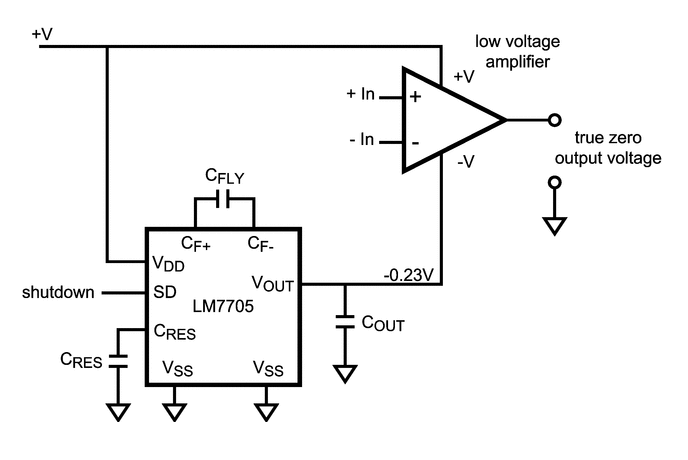
To achieve a true ground output, you need a negative voltage supply. There are dedicated ICs designed to provide a small negative power supply to op-amps so that they can output true ground. One such example is the Texas Instruments LM7705, a “Low Noise Negative Bias Generator”. This IC only generates -230mV, which allows the designer to use CMOS-based op-amps which usually have a maximum supply voltage of 5.5V.

The typical application schematic for the Texas Instruments LM7705, a 'Low-Noise Negative Bias Generator' for the negative supply of an op-amp. This allows the op-amp to output true 0V. Image from http://www.ti.com/.
Examples
Below are some examples of op-amps that stand out from the crowd for some reason, be it popularity, years in service, or functionality wise.
| Manufacturer Code | Description | Approximate Price (1 unit, US$) |
|---|---|---|
| AD860x | Good for high precision stuff! Awesome for photo-diode amplification (both current-to-voltage and voltage-to-voltage configurations). | $3.50 |
| LM324 | A common op-amp that has been around for along time, this can operate of a single supply and can swing right to ground, but cannot swing to the rail voltage. | |
| LM833 | One of the cheapest 'audio' op-amps available (about US$0.20 as of 2011). Features a high GBW for it's price. | |
| OPA695 | This is a ultra-wideband, current-feedback op-amp. If you need an op-amp with a ridiculously high gain-bandwidth product, this is along the lines of what you want to use. It has a GBW of 1700Mhz and a maximum slew-rate of 4300V/us. | $3.50 |
Isolation Amplifiers
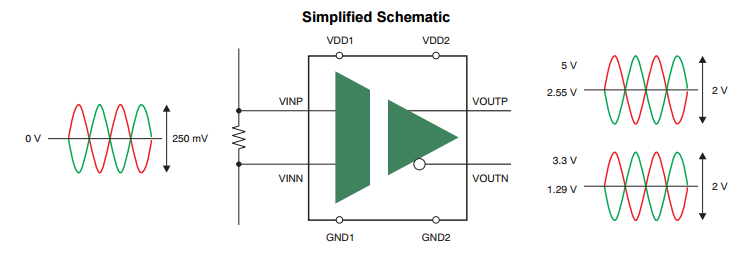
Isolation amplifiers provide galvanic isolation between the input (sensor) and output (measurement circuitry). They are used to protect the sensor measurement and recording circuitry (e.g. a microcontroller with on-board ADC) from dangerously high voltages at the sensor, and also the opposite, to protect the sensor environment from potentially dangerous voltages on the rest of the system.

A simplified schematic of the Texas Instruments AMC1200, a fully-differential isolated amplifier. Image from http://www.ti.com/.
A common application would be to isolate and amplify the voltage across a current-sense resistor on a high-power motor, or to protect humans with medical sensors connected to them from the measurement system.
Basic isolation amplifiers require two power supplies (one for each side of isolation), while others incorporate built-in transformers so that you only have to provide one power source.