DIODES
TVS Diodes
| Date Published: | |
| Last Modified: |
Overview
TVS (transient voltage suppressor) diodes are used to protect traces from high voltage spikes. They work by shunting currents when the voltage exceeds the avalanche breakdown potential. They are basically high-power Zener diodes. They start conducting at a preset voltage and are tailored for low on-times.
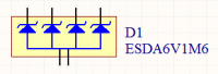
They can be grouped into IC packages called arrays. A typical schematic symbol for a diode array is shown below.

Important Parameters
| Parameter | Symbol | Units | Description |
|---|---|---|---|
| Breakdown Voltage | \( V_{breakdown} \) | \( V \) | Also called the reverse breakdown voltage. This is the reverse voltage (cathode-to-anode) at which the diode "begins" to conduct. The point at which the diode begins to conduct is usually specified as a fixed current, typically 1mA. Also see [standoff voltage](/electronics/components/diodes/tvs-diodes/). |
| Rated Power | \( P \) | \( W \) | The maximum power the TVS diode can dissipate, for a specified time period. Typical values range between 400W-1.5kW. |
| Standoff Voltage | \( V_{standoff} \) | \( V \) | This is the reverse voltage that the diode can withstand without drawing "any" current. This is one of the most important parameters, as you usually match this voltage to the maximum operating voltage of the wire you are connecting it to. Note that there is a small amount of current drawn at this voltage, this is called the reverse leakage current. |
They are part of a family of components used for ESD (electro-static discharge) protection, which also includes zener diodes. TVS diodes can handle large amounts of peak power (hundred’s or thousands of Watts), but Zeners have a tighter voltage tolerance. TVS diodes have more capacitance than Zeners, which could be detrimental in some circumstances (e.g. when protecting the gate signal on a MOSFET).
They come in either uni-directional or bi-directional flavours. Uni-directional diodes block up to the rated voltage in one direction, and behave like a normal conducting diode in the other. Bi-directional block up to the rated voltage in both directions (good for protecting AC waveforms). Use uni-directional diodes if possible, they are cheaper, and they have much faster turn-on times than their bi-directional counterparts (e.g. 4ps compared to 4ns).
Leakage Current
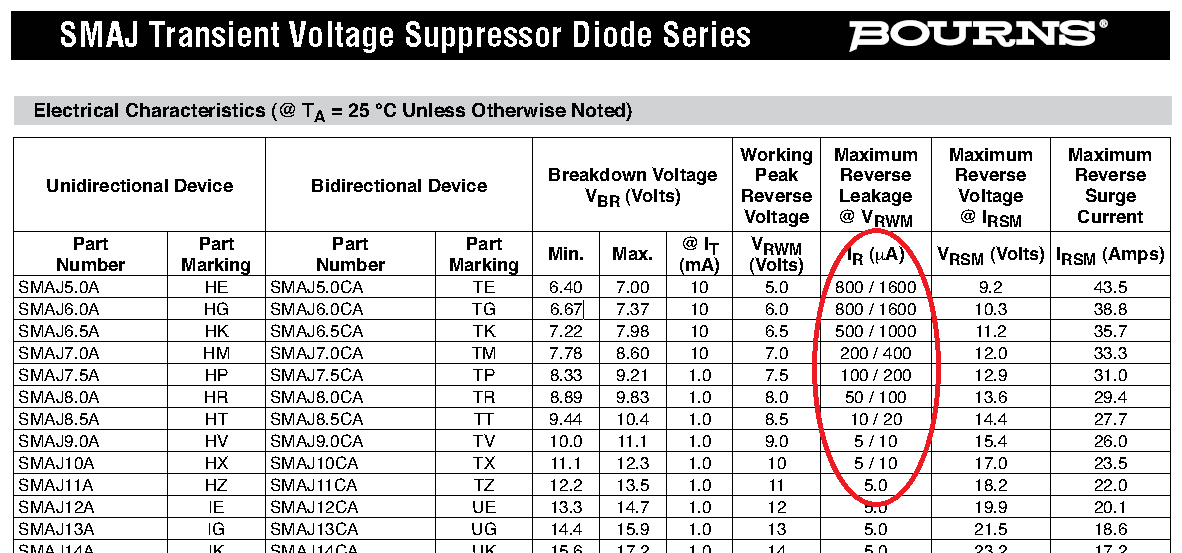
The reverse-leakage of TVS diodes decreases as the stand-off voltage increases. Be warned, the leakage current of TVS diodes which have low voltage stand-offs (e.g. <10V), can have large leakage currents! A 5V stand-off TVS diode typically has a reverse-leakage current of around 500uA, but TVS diodes with a stand-off voltage of 10V or higher have a reverse-leakage of 1uA or less. Note that at low stand-off voltages, the leakage current of a bi-directional diode can be double that of a uni-directional diode for the same stand-off voltage.

For more information, see the ESD Protection page.
Reverse Polarity Protection
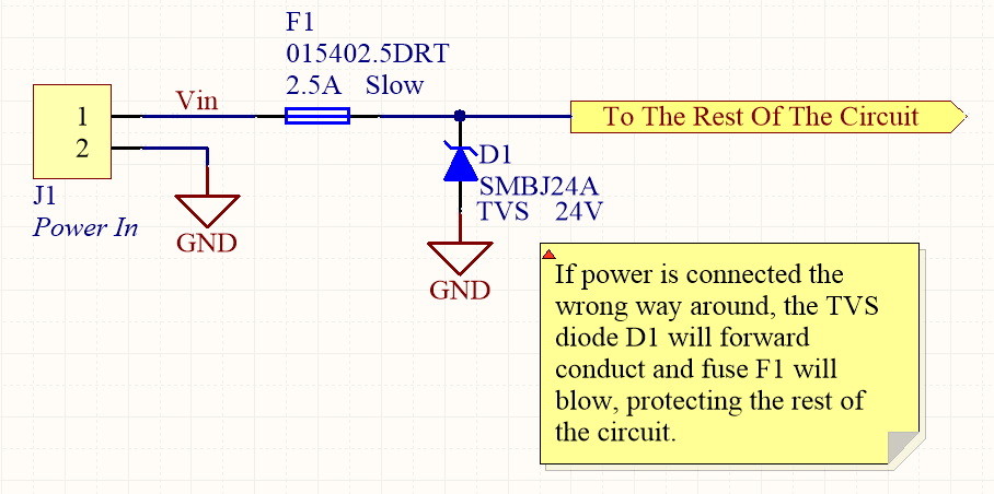
Unusually, TVS diodes. along with a fuse or other current-limiting device, can act as a very good reverse-polarity protection mechanism on inputs to a PCB. They are usually present on a voltage rail input for the primary reason of reducing ESD. However, if the V+ and GND are connected to the PCB the wrong way around, the TVS diode will forward conduct and clamp the voltage to a normally non-destructive 0.7-1.5V. A current-limiting device like a fuse also has to be present to prevent the TVS diode from overheating.
They are especially suited to this role (when considering other diodes) as the are usually built to dissipate large amounts of heat.

In the schematic above, the fuse will quickly blow if the power supply is connected to the input connector the wrong way around.
Low Capacitance
There are a family of TVS diodes called low-capacitance (or ultra-low) TVS diodes. They have much less capacitance than standard TVS diodes (typical capacitances are between 0.4-0.9pF), and are designed for protecting high-speed data lines such as those used in USB, HDMI, DisplayPort, and Ethernet communication protocols and also for RF antennas such as GPS, FM radio and NFC antenna lines.
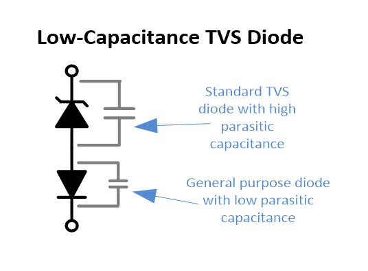
This low capacitance is achieved by adding a forward-biased general purpose diode in series with the usual reverse-biased TVS (zener-style diode). The schematic symbol for a low-capacitance TVS diode is shown below:

The internal schematic of a low-capacitance TVS diode, showing the forward-biased general purpose diode added in series to greatly reduce the total capacitance of the component.
The forward-biased general purpose diode has a much smaller parasitic capacitance than the zener diode. Because the parasitic capacitances are in series (grey capacitors in diagram), the total capacitance of the component is greatly reduced!
Special-Purpose TVS Diodes
RS-485 TVS Diodes
TVS diodes built specifically for protecting RS-485 communication protocol bus lines are bi-directional and have two different hold-off voltages to meet the RS-485 spec. They normally include the character sequence “SM712” in their part name (e.g. SM712-02HTG by Littelfuse and SM712-TP by Micro Commerical).

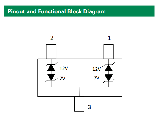
The pintout and functional block diagram of the SM712-02HTG TVS diode, designed specifically for protecting RS-485 bus lines. Image from http://www.littelfuse.com/~/media/electronics/datasheets/tvs_diode_arrays/littelfuse_tvs_diode_array_sm712_datasheet.pdf.pdf.
More information on these diodes can be found in the Specialised TVS Diodes section on the RS-485 Protocol page.