DIODES
Diodes
| Date Published: | |
| Last Modified: |
Child Pages
Overview
Diodes are passive semiconductor components consisting of a single P-N junction. Their main property is that they only allow conduction of current in one direction, which makes them a useful component in many electronic circuits.
Parameters
These are some of the important parameters shared by all types of diode (in a rough order of importance):
| Parameter | Symbol | Description |
|---|---|---|
| Maximum Continuous Forward Current | \( I_{f(cont)} \) | The maximum continuous current the diode can withstain, usually limited by overheating. Typically 20-500V. |
| Forward Voltage | \( V_f \) | The forward voltage drop, usually rated at maximum continuous current (\( I_f \) ). An ideal diode would have no forward voltage drop. Schottky diodes have the lowest forward voltage drop of any diode. Generally, the smaller the forward voltage drop, the larger the reverse-leakage. The higher the temperature, the smaller the forward voltage drop. Typically 0.3-1.2V. |
| Reverse-leakage Current | \( I_R \) | The leakage current when the diode is reverse-biased at the stand-off voltage. An ideal diode would have no reverse-leakage current. Generally, the smaller the reverse-leakage current, the larger the forward voltage drop. The higher the temperature, the higher the reverse-leakage current. Typically 10nA-1mA. |
| Peak-surge forward current | \( I_{FSM} \) | The forward current the diode can handle for a small amount of time. The exact time depends on the standard used to calculate this value (usually JEDEC). The is normally so you can determine the diode can handle inrush current/inductive energy pulses of a particular circuit. |
Some other important properties of diodes are their ability to prevent conduction until a certain, configurable breakdown voltage, and a conduction current that is related to the square of the voltage across it. On schematics, they have the designator “D”, and the following symbol (for a general diode).

Diodes come in many component packages, one of the most common being the through-hole DO-41 package. They also come in standard SMD packages. It is a good idea to add polarity marks to the silkscreen layer on diode footprints. The picture below shows polarity marks being added to a diode with a 0603 footprint.

Polarity
Most diodes have their polarity marked with a single line near the cathode (the “more negative” end when conducting current). They will let current flow from anode to cathode but not in the other direction.
Schottky Diodes
Schottky diodes are special diodes that have a lower voltage drop than standard diodes (typically 0.3V instead of 0.7V). They are used in applications where the input voltage is small, and in high power applications in where the power consumption of the diode needs to be kept to a minimum. The standard schematic symbol for a schottky diode is shown below (note the curls on the bar, which differs it from the standard diode symbol.

Zener Diodes
Zener diodes are diodes which have a specified reverse blocking voltage at which they breakdown and begin to conduct. They are similar to TVS diodes, but generally have a more defined and precise breakdown voltage, but a lower power rating. Also, shunt voltage references are similar in concept to zener diodes, except that they are more precise but can’t dissipate as much power.
Uses for zener diodes include:
- Low power/simple voltage reference
- Over-voltage protection for low power applications (use TVS diodes to dissipate high energy voltage spikes)
- To turn on a sub-circuit once a certain voltage level is reached (e.g. an LED in a simple battery charging circuit)
You can purchase Zeners with a reverse voltage drop as low as 1.8V all the way to above 100V. For voltage drops less than 1.8V, you can stack (i.e. place in series) multiple normal or schottky diodes in forward bias.
For more information, see the ESD Protection page.
Photo Diodes
Note these are not be confused with photo-transistors, which are similar, but technically not photo diodes. Photo diodes have a faster response time than photo-transistors.
Avalanche Photo-diodes (APDs)
Avalanche photo-diodes (APDs) are constructed in a similar manner to PIN diodes. The major difference is that they are operated with a much larger reverse voltage (100-200V for silicon based ones). This causes the avalanche effect (impact ionization) whenever photons strike the sensor, giving a current-gain of around 100. The current gain is roughly proportional to the applied reverse voltage, and for this reason some special avalanche diodes have been made which have a reverse breakdown voltage of over 1500V, allowing much higher gains (e.g. 1000).
Sometimes they can be operated above their maximum reverse voltage for short periods of time, giving even larger gains! When operated in this fashion, it is called Geiger mode.
APDs are used in range-finders and optical communications.
Bridge Recitifers
Bridge rectifiers are 4 diodes connected in such a way that they rectify an AC voltage waveform into a DC one. The image below shows a bridge rectifier being used after a transformer to convert 12Vac into 12Vdc. Note that the frequency of the ripple will be twice the AC input frequency (2x 50Hz = 100Hz).

Bridge rectifiers can have snubber elements attached to each diode. This helps reduce the high-frequency noise which can be induced when the diodes themselves switch on/off, due the leakage inductance and parasitic capacitance of the transformer (which cause oscillations when the diodes essentially change the output impedance). Typical values for the snubber circuit are a 47pF capacitor in series with a 2kR resistor.
Temperature Sensors
Diodes can be used as temperature sensors, as their forward voltage changes depending on the temperature. Most 3-pin active linear temperature sensors use a diode for the temperature measurement, along with additional circuitry to linearise and scale the reading. See the Temperature Sensors page for more information.
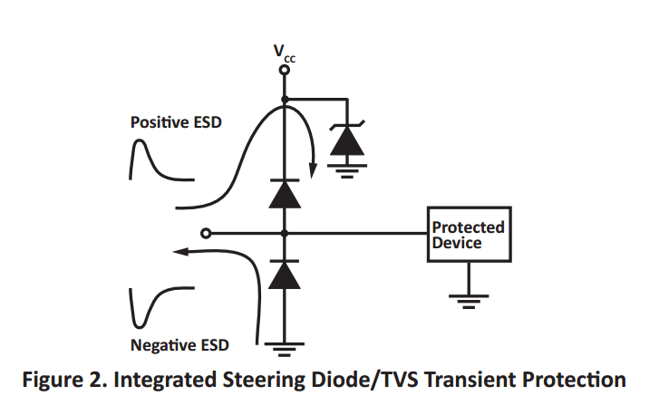
Steering Diodes
Steering diodes is a name given to a configuration of two or more diodes that changes the direction of current depending on the polarity of the waveform.
They can be used to provide transient ESD protection.

Steering diodes can be used for transient ESD protection. Image from http://www.protekdevices.com/Assets/Documents/Technical_Articles/ta1002.pdf.
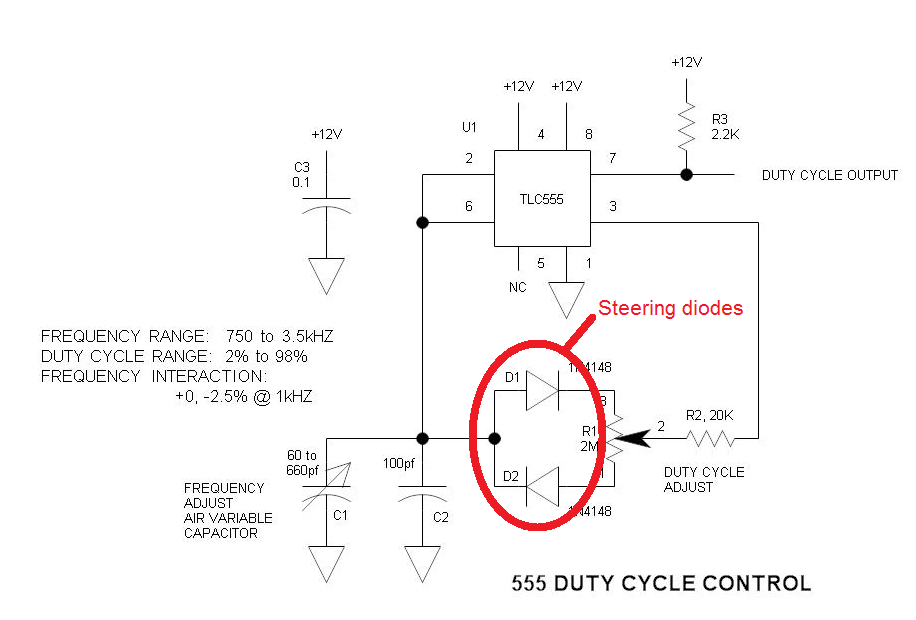
They can be used alongside a potentiometer and 555 timer to create a PWM circuit.

Schematic highlighting the steering diodes used to generate a variable duty-cycle PWM circuit using a 555 timer, without changing the frequency. Image from http://www.electroschematics.com/6950/555-duty-cycle-control/ (with modifications).
Can Diodes Share Current?
The short answer: No!
The slightly longer answer…
Diodes have a negative resistive thermal co-efficient, that is, as they warm up, their resistance decreases. This means that if you connect two or more diodes in parallel to share the current, one will heat up a bit faster than the other, start to conduct more, heat up even further, start to conduct even more, e.tc e.t.c, until one is conduction almost all the current. This even occurs when the diodes are “identical”, due to the fact their will be small differences in any two identical diodes.One way to prevent one diode from gobbling all the current is to add current-sharing resistors to each diode leg. They should be identical in resistance and have to drop at least 0.3-0.4V (when the diode has a nominal voltage drop of around 0.7V) to be effective.