COMMUNICATION PROTOCOLS
UART Communication Protocol
| Date Published: | |
| Last Modified: |
Overview
UART (Universal Asynchronous Receiver/Transmitter) is a lower-voltage, microcontroller friendly equivalent of the RS-232 digital data transmission protocol with origins dating back to the 1960’s. It was designed as a communication protocol to talk between DTE (data terminal equipment) and DCE (data communication equipment). It is universal in the sense the timing, voltages, flow control and error checking can be configured.
| Drive Type | Single-ended |
| Num. Wires (excl. GND) | 2 (TX/RX) or 4 (TX/RX and RTS/CTS) |
| Duplexity | Full |
| Connection Topology | Point-to-point |
| OSI Layers | Layers 1 (physical) and 2 (data link) |
It is commonly used today as a simple, two-way node-to-node serial communications protocol between devices on a circuit board or possibly over a cable. Because of it’s low voltage and single-ended nature, it is not very noise resilient, and is usually replaced with a more robust protocol such as RS-232 or RS-485 when communication occurs over any significant cable length or in a noisy environment.
Terminology
Sorted in alphabetical order.
| Term | Description |
|---|---|
| CTS | CTS is an initialism for Clear To Send. See the Flow Control section for more information. |
| DCD | DCD is an initialism for Data Carrier Detect. See the Flow Control section for more information. |
| DCE | DTE is an initialism for Data Communication Equipment. It was a term created when UART was first developed to describe electronic devices which transmitted/received data and connected to terminals (which were termed DTE's). See the Flow Control section for more information. |
| DTE | DTE is an initialism for Data Terminal Equipment. It was a term created when UART was first developed to describe electronic devices which displayed data and connected to modems (which were termed DCE's). See the Flow Control section for more information. |
| DTR | DTR is an initialism for Data Terminal Ready. See the Flow Control section for more information. |
| RI | RI is an initialism for Ring Indicator. See the Flow Control section for more information. |
| RTS | RTS is an initialism for Request To Send. See the Flow Control section for more information. |
| RxD | RxD is an acronym for Receive Data. See the Flow Control section for more information. |
| TxD | TxD is an acronym for Transmit Data. See the Flow Control section for more information. |
| UART | UART is an initialism for Universal Asynchronous Receiver/Transmitter. |
| USART | USART is an initialism for Universal Asynchronous/Synchronous Receiver/Transmitter. ATMEL uses this term to describe the peripherals on its ATmega range of microcontrollers that support the standard asynchronous protocol as well as a synchronous (clocked) protocol. |
| Voting | Voting describes a error-checking process in which the same bit of UART data is sampled multiple times and then a vote occurs to determine it's state. |
Protocol
The long history of RS-232 like serial communication means that UART is synonymous/compatible with many physical and protocol layer variations such as:
- CMOS UART
- RS-232
- RS-423 (differential)
- RS-485 (differential)
- DMX512 (commonly used to control stage lighting and effects)
- MIDI
- LIN Bus
- IrDa
Connectors
UART is a protocol that has no one single recognizable connector. Because it is commonly used in conjunction with RS-232 or RS-485 protocols, the D subminiature connectors are commonly associated with the UART protocol. However, because UART is a very common microcontroller peripheral and can be used for short, permanent on-PCB communications between microcontroller and 3rd party device, it is also commonly implemented without any connector at all (pin-to-pin on PCB), or is routed from microcontroller directly to 0.1” header pins for things such as debugging (a debug UART is very common on embedded devices).
Transmission Speeds
UART, by today’s standards, is a slow transmission protocol. However, it is still fast enough for tons of applications. The commonly supported baud rate speeds are:
- 600, 1200, 3400, 4800, 9600, 14400, 19200, 28800, 38400, 56000, 57600, 115200, 128000, 256000, 460800, 921600
I have had basically no issues using speeds up to 460800 baud in embedded systems (either talking to another embedded system, or to a computer through a virtual COM port). However, 921600 baud has not worked for me in some situations.
Some devices also support custom baud rates.
Flow Control
The flow control is a way of detecting when the receiver or transmitter is ready to accept or send new data. The UART protocol provides a few (all optional) methods for flow control:
- Hardware RTS/CTS lines
- Software XON/XOFF flow control
RTS/CTS
This is done by various additional connections to the standard transmit, receive and ground wires. The two most common are CTS and RTS. Typically, a micro-controller may have one or two UART peripherals that support this feature, while the rest are just basic non-flow control UART’s.
A small amount of power can be extracted from the RTS and CTS lines for powering low-power devices.
The following tables lists all of the flow control signals (as well as the data signals), with respect to the device in question. Matching signals are grouped together.
| Signal | Port Type | Description | DB-25 Pin | DE-9 Pin |
|---|---|---|---|---|
| DTR (Data Terminal Ready) | Output | DTE drives this to indicate to the DCE that it is present. | 5 | 4 |
| DCD (Data Carrier Detect) | Input | DCE drives this when it is connected to the telephone line. | 8 | 1 |
| RI (Ring Indicator) | Input | The DCE drives this when it has detected a phone call. Note that there is no matching signal going the other way. | 22 | 9 |
| RTS (Request To Send) | Output | DTE drives this to tell the DCE to get ready to receive data. | 4 | 7 |
| CTS (Clear To Send) | Input | Driven by the DCE when it is ready to accept data. | 5 | 8 |
| TxD (Data Transmit) | Output | The DTE sends data to the DCE over this line. | 2 | 3 |
| RxD (Data Receive) | Input | The DCE sends data to the DTE over this line. | 3 | 2 |
| Common Ground (GND) | n/a | The common ground for all signals. | 7 | 5 |
| Protective Ground (PG) | n/a | The protective ground. This is usually just connected up to the common ground on the PCB. | 1 | n/a |
Rule-of-thumb: Most RS-232 serial interfaces with a male 9 or 25 pin connector are DTE’s, most with a female 9 or 25 pin connector are DCE’s.
Most often, manufacturers label the UART pins as DTE’s. In this case, you have to swap all connections with their matching line. So TxD of device 1 is connected to RxD of device 2, RxD of device 1 is connected to TxD of device 2, RTS of device 1 is connected to CTS of device 2, e.tc.
Error Checking/Noise Immunity
The only error checking a UART has by specification is parity checking (additional error features may exist).
You may notice when sending lots of characters across a UART that some appear to be corrupted. These can be a real bummer if you are using UART to transmit lots of data (for say a data logging application). The best ways to improve noise immunity are:
- Slow down the transmission rate to the slowest acceptable speed. Far less errors occurs at 9600 baud than say, 57600 baud.
- Enable parity checking (does not completely fix the problem!)
- Enable voting algorithms if the transmitter or receiver support it.
- Similarly, enable oversampling if the transmitter or receiver support it (very similar to voting).
- Make the UART transmission lines as short as possible and with as little capacitance as possible.
- Shield the UART cable (not so important)
- Implement a checksum algorithm into the receiver and transmitter, such as a CRC. The UART protocol does not support this natively, you will have to use a 3rd party library/write the code to do this yourself. Even when using a simple checksum algorithm such as exclusive or (XOR), this is probably one of the most fool proof methods for error checking.
Break Signal
The break signal is not a character, but a special signal which can be sent from transmitter to receiver to indicate an event.
The transmitter sends a break signal by driving it’s TX line low for a period longer than one frame. There are two types of breaks, short breaks and long breaks. A short break is when the TX line is driven low for a period of between 1 and 2 frame lengths, and a long break is when it is driven low for a period of more than 2 frame lengths.
Higher-Level Protocols
Do you need a higher-level communication protocol that works over a UART connection? See the SerialFiller library on GitHub (written in C++). SerialFiller uses a publish/subscribe mechanism and works well on point-to-point serial connections such as UART.
Terminal Programs
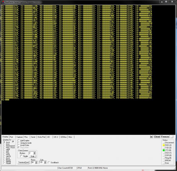
RealTerm (3.5/5)
Website: http://realterm.sourceforge.net/
A easy to use and powerful terminal program for Windows. Stolen from the website, it’s description is:
a terminal program specially designed for capturing, controlling and debugging binary and other difficult data streams. It is far better for debugging comms than Hyperterminal. It has no support for dialing modems, BBS etc - that is what hyperterminal does.
It can view and send binary, hex, ASCII, ANSI, integers (both signed and unsigned, 8 or 16-bit), floats and more. Support for half-duplex communication as well as I2C! Does not lag/hang at all (including when you disable the COM port while it is still running). You can run multiple RealTerm apps at the same time, to get data from multiple UART ports simultaneously. It can add timestamps to received UART messages, which is useful for data logging.

I have noticed a few bugs with RealTerm, especially when it comes to changing the number of rows and columns, and scrolling back through received data (the scrollback variable is buggy also).
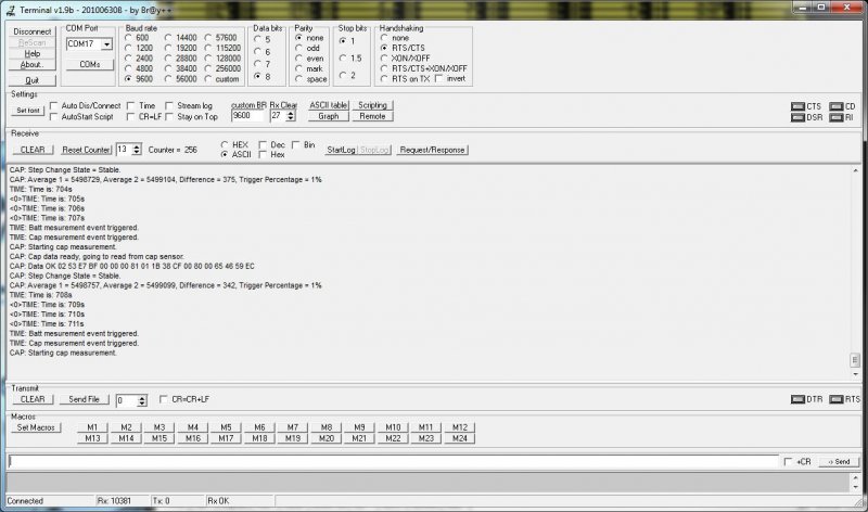
Terminal by Br@y (3.5/5)
Website: https://sites.google.com/site/terminalbpp/
A simple and tidy Windows terminal program. Personally, it doesn’t get the same amount of respect as RealTerm because of it’s simplicity and slightly buggy nature. When decoding into hex, the program can hang if your receiving large amounts of data. It can also hang if you disable the COM port while it is still connected.

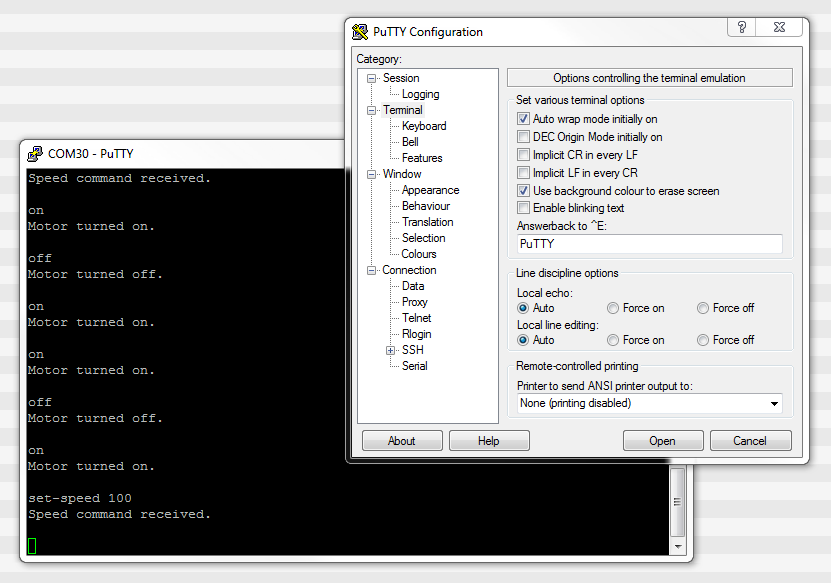
PuTTy (4/5)
Website: http://www.chiark.greenend.org.uk/~sgtatham/putty/
PuTTY is a free implementation of Telnet and SSH for Windows and Unix platforms, along with an xterm terminal emulator.
If your running windows, PuTTY is a very handy application to have if you want to emulate the command-line style interface of a UNIX-like system. Although the debugging and capturing features are not as good as say, RealTerm, it offers character-by-character input and proper response to pressing ‘special’ keys such as enter (which RealTerm doesn’t allow, instead you have to enter a string and then press send). This may sound like a very small difference, but this feature does come in useful! I find it very handy when using FreeRTOS and the CLI (command-line interface) extension, which allows you to communicate from a pc to a embedded system using a command-line style interface (as in the picture to the right).

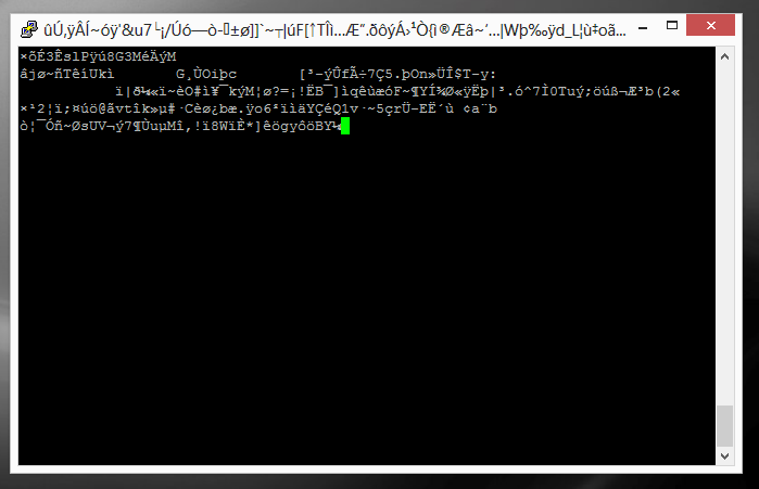
I have discovered one bug in PuTTY…if it receives a large number of characters all at once (which is common when printing debug messages from an embedded system, and for some reason, the string is not null-terminated, and starts printing gobble-de-gooch from random memory locations), PuTTY can freeze, and needs to be restarted. In this situation, it can also print the message “PuTTyPuTTyPuTTy” many times over across the COM port you are debugging. Weird.

9-Bit Addressing
9-bit addressing was employed when using a multi-drop configuration to prevent slaves from wasting processor time in decoding every byte on the bus to see if it was addressed to them. A 9th bit is sent out after every byte, and is used to signal if the previous 8-bits where an address (which the slaves have to listen to), or just data (which can be ignored).
Radiation Hardening
Some UART protocols have radiation tolerant devices, such as the DRS4485, an Dual RS-485 Interface Transceiver made by Aeroflex.
RS-232
RS-232 is a very similar protocol to UART, and a UART to RS-232 converter is one of the most popular communication protocol converters you will see in an embedded system.
For more information, see the RS-232 page.
RS-485
RS-482 is another very common protocol that UART is converted to and from. It is usually chosen over RS-232 when longer distances and/or larger noise immunity is needed. For more information, see the RS-485 page.
Cables
You can get null-terminated USB-to-USB serial port emulator cables. These are awesome for transferring data between two computers (or any 2-USB host devices) without reverting to a true USB-to-USB A cable (which requires use of a more complicated protocol).
FTDI makes one such cable called the USB to USB cable.
If you are interested in routing between two COM ports on the same computer, you could use one of these, however, it is normally much easier to do it purely in software with a serial bridge instead.
Powerline Transceivers
The SIG60 is an example of a powerline transceiver.
Creating A Serial Port Bridge
There are occasions when you want or need to send serial data between two pieces of software on the computer, or between two hardware devices both connected to the computer. An example would be to unit test a PC-based serial communications protocol you have written without writing the unit-test code on the microcontroller. There are software programs that emulate a serial port bridge, but in my experience I found these are every buggy or cost money.

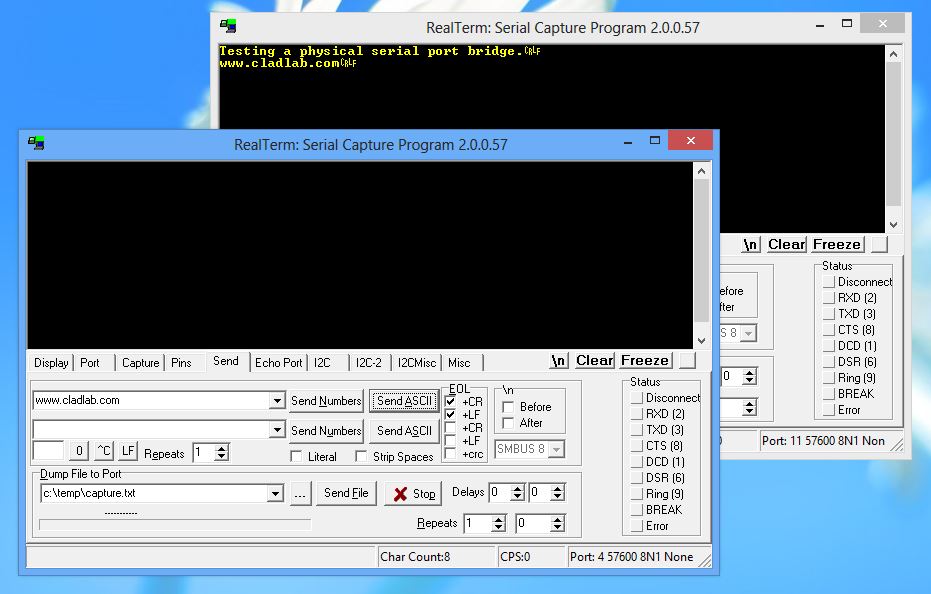
You can create a rudimentary serial bridge to connect to pieces of software together by connecting two USB-to-UART (or USB-to-RS232) converters together, crossing the RX and TX lines over. Although not a very permanent solution, this is good for simple tests. The following image shows a hardware-based serial port bridge with a terminal on each end.
Related Content:
- RS-232 Protocol
- I2C Communication Protocol
- 4-20mA Current Loops
- July 2016 Updates
- USB-to-Serial Converters
Tags:
- UART
- communication protocol
- USART
- microcontroller
- serial
- 8n1
- universal asynchronous
- receiver
- transmitter
- RX
- TX