COMMUNICATION PROTOCOLS
CAN Protocol
| Date Published: | |
| Last Modified: |
Overview
The CAN (Controller Area Network) protocol is a serial-based digital communication protocol originally developed by BOSCH. It was initially developed for use in the automotive industry. It makes use of priority-based message arbitration. The voltage is not part of the standard, and operating voltages of 5V or 12V are common.
If you are looking for help interfacing with SocketCAN from the Linux command-line, see the How To Use SocketCAN With The Command-Line In Linux page.
If you are looking for help controlling a SocketCAN interface from C software, see the How To Use SocketCAN With C In Linux page.
A alternative communications protocol used in similar applications is the LIN protocol.
Bit Rate And Transmission Distances
The following equation can be used as a rule-of-thumb to calculate the maximum transmission speed for distances larger than 50m.
where:\(BR\) = bit rate (in Mbit/s)\(L\) = length (in m)
A table of common distances/transmission rates is shown below:
| Speed | Distance** |
|---|---|
| 1Mbit/s | 25m |
| 800kBit/s | 50m |
| 500kBit/s | 100m |
| 250kBit/s | 250m |
| 125kBit/s | 500m |
| 50kBit/s | 1000m |
| 20kBit/s | 2500m |
| 10kBit/s | 5000m |
Arbitration
The CAN network uses priority-based message arbitration. The drivers to the CAN line(s) are open-drain. This means that if a node writes a 0 (dominant), it will over-write a 1 (recessive). This is also called a “wired AND” configuration.
Encoding
The CAN bus uses NRZ encoding.
Any sequential sequence of 5 bits of the same type requires the transmitter to insert a bit of the opposite polarity. Consequentially, the receiver has to remove this bit from the incoming data stream.
Frame Types
Data Frames: Used to transmit a data payload of up to 8 bytes. Very similar frame structure to a remote frame.
Remote Frames: Used to request data. Contains no data payload itself. Very similar frame structure to a data frame.
Error Frames: Transmitted when a node encounters an error during communication. An error frame contains only an error flag and an error delimiter.
Frame Structure
Dominant bits are logic level 0, while recessive bits are logic level 1.
Standard Data/Remote Frame (11-bit Identifier)

SOF bit: A dominant start of frame bit marks the start of a message. It is used to synchronize all the nodes on a bus after being idle. Transmitted by the sender.
11-bit Identifier: This 11-bit value is used to identify the contents packet. It is also used to prioritize packets, and identifiers with lower values will have higher priorities.
RTR bit: The Remote Transit Request bit differentiates between data and remote frames (a remote frame is a request for data). In data frames, this bit is dominant and in remote frames this bit is recessive. Thus, data being returned from a request always has a higher priority than a packet requesting the data (with the same identifier).
IDE bit: The Identifier Extension bit distinguishes between standard and extended frames. In standard frames this bit is dominant, in extended frames this bit is recessive.
r0 bit: This bit is reserved for future CAN bus standards user. Always recessive.
4-bit DLC: The 4-bit Data Length Code (DLC) contains the number of bytes that will be transmitted. Since the range of data bytes can vary between 0-8, we need 4 bits to specify this value. DLC values from 9-15 are not allowed.
0-8 bytes Data: This is the data payload. Up to 8 bytes can be sent in a single packet, as long as it is a data frame. For a remote frame, there must be no data bytes.
16-bit CRC: The Cyclic Redundancy Check (CRC) is used to detect errors in the packet. It consists of a 15-bit CRC value followed by a delimiter.
2-bit ACK: Based on the value of the CRC, the receiver uses first acknowledge bit to either positively or negatively acknowledge the message. The 2nd bit is a delimiter.
7-bit EOF: The End Of Frame is marked with 7 recessive bits.
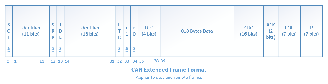
Extended Data/Remote Frame (29-bit Identifier)

The extended frame is the same as the above standard frame, except for the differences described below:
SRR bit: The Substitute Remote Request bit is transmitted in extended frames at the position of the RTR bit in standard frames. It is always recessive.
_**IDE bit: **_The Identifier Extension bit distinguishes between standard and extended frames. In standard frames this bit is dominant, in extended frames this bit is recessive.
r1: An additional reserve bit for extended frames only. Must be recessive.
18-bit Identifier: Another 18-bits that can be used as part of the identifier, giving a total of 29-bits for the identifier in an extended frame. 11-bit identifiers have a higher priority than 29-bit identifiers.
Message Lengths
There are two different message lengths supported by the CAN protocol.
- CAM Base Frame (CAN2.0A)
- CAM Extended Frame (CAN2.0B)
Errors
There are 5 different types of errors:
- Bit Error: The transmitter monitors the bus level as it sends bits. If the level is not the same as what it is transmitting, a bit error occurs. Physical layer error.
- Stuff Error: If 6 or more consecutive bits of the same type are found. Physical layer error.
- Format Error: Data-link layer error.
- CRC Error: When the computed CRC does not match the one received in the message packet. Data-link layer error.
- Acknowledge (ACK) Error. Data-link layer error.
CAN Controller IP
Most popular FPGA vendors provide pre-licensed (you don’t have to pay anything to use it!) CAN controller IP cores for use within their FPGAs.
Xilinx provides the CAN 2.0B and CAN-FD Controller IP core which is compatible with the Ultrascale, Zynq-7000, 7-series, 6-series and other Xilinx FPGAs.
Standards
ISO 11898
ISO 11898 is a widely followed basic CAN standard, defining parts of the physical and data link layers. There are many different versions of this standard:
- ISO 11898-1:2015 - Specifies data-link layer and physical signalling
- ISO 11898-2:2003 - Specifies the high-speed transmission (up to 1Mbit/s) medium access unit (MAU). This has been revised by ISO 11898-2:2016.
- ISO 11898-2:2016 - Specifies the high-speed physical media attachment (HS-PMA) component for the CAN bus.
- ISO 11898-3:2006 - Specifies low-speed, fault tolerant CAN bus information transfer between road vehicles.
Related to ISO 11898 is ISO 16845, which details test suites and test requirements for checking CAN bus/controller conformance to the specs.
CANopen
CANopen was developed for embedded devices in automation systems . It defines the OSI network layers that the basic CAN standards leaves unspecified, which includes the network layer and above.
NEMA 2000
A communication protocol for ships which is based on the CAN standard.
PeliCAN
PeliCAN is a CAN controller “mode” named by NXP with the arrival of their SJA1000 stand-alone CAN controller ICs, which were a successor to the PCA82C200 CAN controller ICs (BasicCAN). PeliCAN supports all of the frame types defined by CAN 2.0B.
PeliCAN mode extensions include:
- Error counters
- Error interrupt
- Single-shot transmission (no re-transmission)
- Listen only mode
- Hot pluggin support
- Acceptance filter extension
- Self reception support (can receive messages sent by self)
SAE J1939-11
Uses a shielded twisted pair. Used in trucks, agricultural and industrial equipment.
Licensing
The CAN protocol and CAN FD protocol are protected with IP rights by Bosch. Any CAN IP modules for a FPGA or ASIC (including self-developed ones!!!), or fixed hardware CAN IP peripherals for microcontrollers must be licensed.

A screenshot of the CAN bus licensing fee details from Bosch. Image from http://www.bosch-semiconductors.de/media/automotive_electronics/pdf_2/ipmodules_3/can_protocol_license_1/Bosch_CAN_Protocol_License_Conditions.pdf.
See http://www.bosch-semiconductors.de/media/automotive_electronics/pdf_2/ipmodules_3/can_protocol_license_1/Bosch_CAN_Protocol_License_Conditions.pdf for more information.
USB to CAN Adapters
Many USB to CAN adapters use a serial DB-9 connector for the CAN side.
One example is the PCAN-USB, which support Windows and Linux.

Drivers
SocketCAN
SocketCAN is a set of open-source CAN drivers and a networking stack for the Linux kernel.
SocketCAN creates a new protocol family called PF_CAN. You can then communicate with the CAN bus with a socket, in the same way you would for the internet protocol (IP).
CAN support was added to the Linux kernel in version 2.6.25.
More information on SocketCAN, including information and code examples on how to send and receive CAN data from the terminal using SocketCAN, see the How To Use SocketCAN With The Command-Line In Linux page or the How To Use SocketCAN With C++ In Linux page.
IC’s
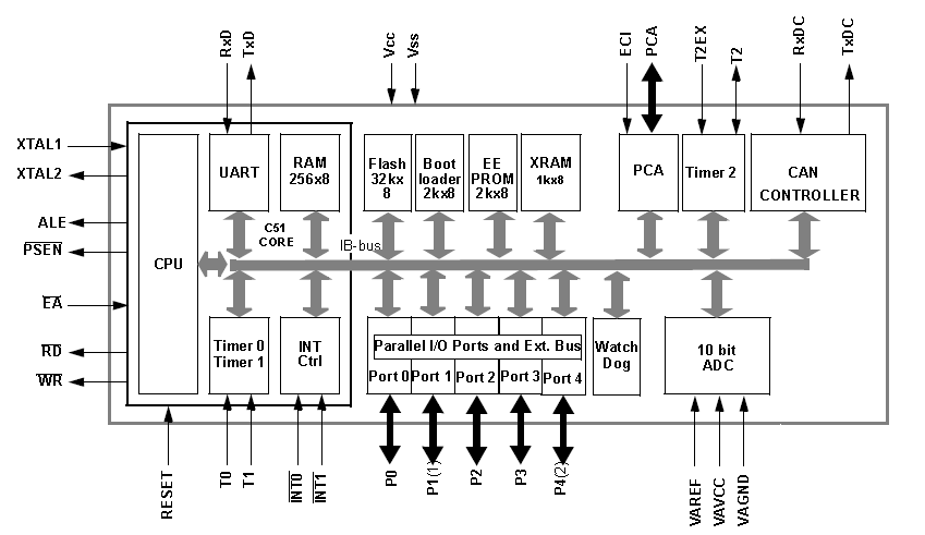
Atmel T89C51CC01 Microcontroller. 8-bit 8051 architecture, with CAN interface. Supports bootloading from the CAN protocol

MCP2515: Microchip CAN Controller.
MCP2551: Microchip Highspeed CAN Transceiver
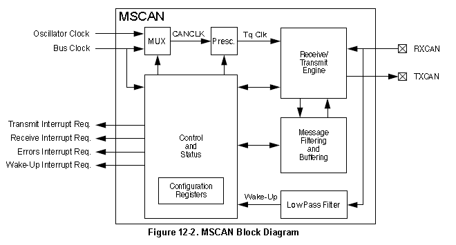
The Freescale MC9SO8D range of microcontrollers have built-in support for both CAN and LIN communication protocols. The CAN peripheral block is called an MSCAN.

Related Content:
- How To Use SocketCAN With The Command-Line In Linux
- How To Use SocketCAN With C++ In Linux
- I2C Communication Protocol
- LVDS (Low-Voltage Differential Signalling)
- July 2017 Updates